A battery management system (BMS) is an electronic system that manages a rechargeable battery pack. Its main functions are:
- Monitoring battery status – voltage, current, temperature, state of health and state of charge
- Protecting the battery from operating outside its safe operating area
- Balancing cells in a battery pack to maintain even wear
- Reporting information for accurate state of charge and warning of faults
- Controlling contactors and relays to connect/disconnect the battery
- Communicating battery information to other systems
The BMS is a crucial component of any battery pack, ensuring safe and reliable operation of lithium-ion and other battery chemistries. A well-designed BMS maximizes battery capacity and lifespan while ensuring safety, ” The PCB Board is the soul of BMS System ” Said by RayMing PCB, Who is one of the best BMS Board manufacturer.
Why is a BMS important?
A BMS is essential for several reasons:
Safety
The BMS monitors individual cell voltages and temperatures to prevent operation outside safe limits. Going above the maximum voltage can be dangerous. At too low a voltage, cells are damaged. Over temperature further accelerates aging. The BMS protects the battery pack by disconnecting it if any parameters go out of limits.
Cell Balancing
Small differences in manufacturing and chemical composition mean the capacities of cells in a pack are not identical. On charging, cells fill up at slightly different rates. Without balancing, some cells will be overcharged while others remain undercharged. Active balancing equalizes all cells by shuffling energy between them.
Accurate State of Charge
The BMS integrates current to calculate coulomb count and estimate state of charge. This prevents over-charging or excessive discharging that shortens battery life. The state of charge value helps optimize use of available energy.
Recorded Diagnostics
The BMS logs operating data like charge/discharge currents, cell voltages and temperatures during the battery lifetime. This data helps engineers analyze battery operation and performance.
Thermal Management
The BMS monitors cell temperatures and activates cooling if required. This avoids cell damage and thermal runaway caused by overheating.
Proper thermal design is a must for lithium battery safety. The BMS calculates heat generation from currents and gives feedback to control the cooling system.
Communications Interface
The BMS communicates vital battery information like state of charge, health, warnings and faults to the charging system, inverter and other equipment.
Contactor Control
The BMS operates contactors to connect or disconnect the battery from the load or charging system when commanded or in response to faults. The precharge system ensures that contactors close with low arcing for reliability.
Battery Management System Design
Designing an effective BMS requires careful consideration of the following aspects:
Basic functionality required
- Cell monitoring – voltage, current and temperature
- State of charge and health estimation algorithms
- Active balancing between cells
- Safety limits and disconnect on faults
Environmental factors
- Temperature range
- Vibration, shock loading
- Ingress protection against water, dust etc.
Communications interfaces
- CAN, RS485, isolated digital
- Protocols – custom, CANopen etc.
Mechanical design and cooling
- Enclosures, mounting brackets
- Connectors, wiring harnesses, fusing
- Cooling system requirements
Cost, size and processing power
- Component choices – microcontrollers, memory, interfaces
- PCB design – layers, component placement
- Firmware efficiency
We will go through these aspects in more detail in the following sections.
Cell Monitoring Hardware
At its core, the BMS needs hardware to measure voltage, current and temperature on every cell. Additional analog inputs may monitor pack voltage and temperatures at different points.
Voltage Measurement
Cell voltage measurement requires high accuracy to detect small variations between cells. The circuit should draw very little current so it does not disturb the cell’s natural voltage.
Common choices for voltage measurement ICs are:
- Purpose designed cell monitoring chips like the TI BQ76952
- High resolution ADCs with multiplexed inputs – Analog Devices LTC6811
- Delta-sigma ADCs with PGA gain – Maxim MAX11068
Multiple cell monitoring ICs can be stacked in series to monitor a large number of cells. High input impedance ensures minimal current draw. Filtering rejects noise while sampling to avoid false tripping.
Cell voltage measurement ICs communicate digitized data to the BMS microcontroller on a serial bus like SPI.
Current Measurement
Current sensors provide data for coulomb counting and cell balancing algorithms. Different approaches are:
- Hall effect sensors detect magnetic field produced by current. Provide electrical isolation. Available for high currents up to 1000A.
- Shunt resistors use Ohm’s law voltage drop to calculate current. Low cost but need isolation amplifier. Limited current range.
- Current sense amplifiers like INA138 detect small voltages across shunt. Usually 0-200 mV inputs.
High frequency sampling by an ADC input eliminates noise in current signals. Careful filtering removes harmonics from inverter operation.
Ideally each cell has a dedicated current sensor for the most accurate balancing. A single current sensor is cheaper but cell to cell differences remain undetected.
Temperature Measurement
Thermistors attached to cells give accurate temperature readings, crucial for safety. Thermistor interfacing requires ratiometric measurements with good ADC linearity. Budget solutions may use simple comparators with over temperature thresholds. High end systems implement RTD sensors with isolated measurements.
Battery Management System Electronics
The BMS electronics can be divided into:
- Measurement circuitry – ICs monitoring cell voltages, current sensors, thermistors etc. as covered earlier. Provides analog voltage and current signals to the BMS controller.
- Microcontroller – Runs state estimation algorithms using measurement data. Implements safety checks, balancing and interface protocols. ARM Cortex M4 designs balance performance and cost.
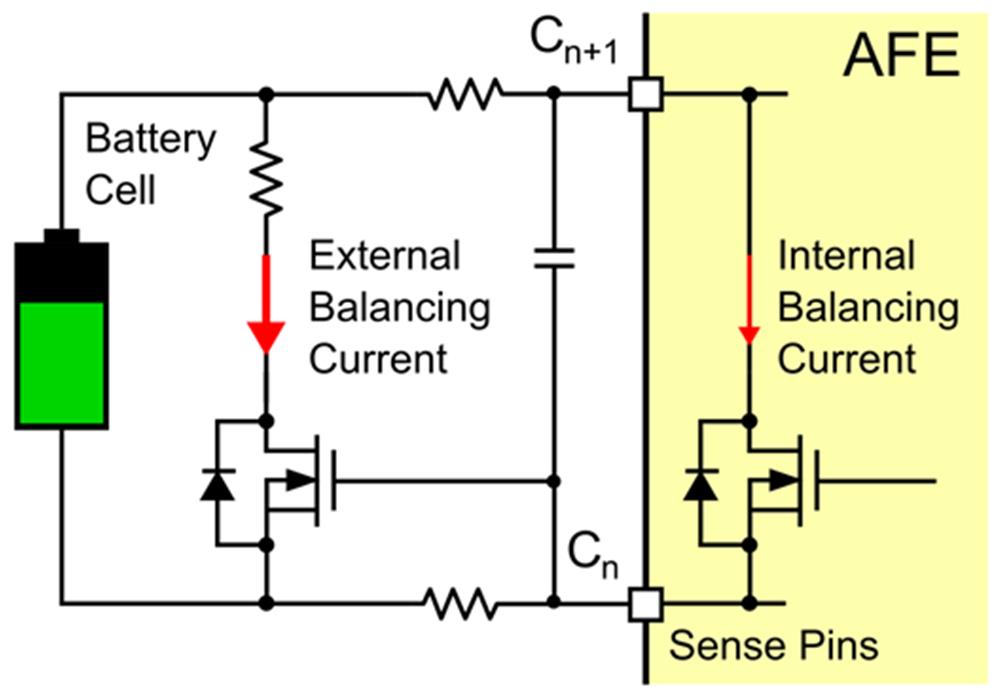
- Cell balancing – Switches like FETs controlled by GPIOs shunt current around cells under program control. This equalizes all cells in a pack. Passive balancing uses resistors while active balancing is more efficient.
- Power supplies – Low noise supplies for analog systems. Step down DC-DCs for MCU and peripheral power. LDOs for ADC references. Backup battery for clock and RAM retention.
- Contactors – Connect/disconnect battery under fault conditions or on command. Controlled by GPIOs with diagnostics feedback. Precharge protects from inrush current.
- Interfaces – Communication interfaces like CAN, RS485 provide data on SOC, health, warnings and faults. May drive warning LEDs.
- Protection – Fuses, TVS diodes, filtering prevents damage from over voltage and high current faults.
The layout interconnecting these subcircuits requires care for signal integrity. Separate analog and digital grounds are tied at a single point. Decoupling capacitors aid power supply stability. Balanced tracing avoids ground loops. Safety standards require reinforcement and testing.
Firmware Algorithms
Advanced firmware algorithms are key to optimal BMS performance and maximizing battery capacity. Major functions implemented in firmware are: